Valerie Sonnenberg
JPL Icy Worlds Sampler
Mechanical Engineering Senior Design
Final Deliverables
I created a 10 minute video encompassing the entire Senior Design experience for our team from start to finish. We also presented a white paper to explain our project. We completed partial functionality and full integration of our project, succeeding in our year-long mission to create a sample-handling mechanism for an Icy World. Please take a look at these final deliverables and find further detail below.

Client and Problem
For our senior capstone project, we have partnered with Jet Propulsion Laboratory to work on the Icy Worlds missions. These missions are centered around traveling to other bodies in our solar system that contain water, such as Europa, the moon of Jupiter. One of the engineering challenges of this mission is delivering surface matter to the various measurement systems on the lander in correct amounts. Our team has been tasked with creating a system that can divide a bulk sample into three discrete sizes and deliver those measured samples to each instrument.

Size
Working space is proportional to 70 x 40 x 20 cm and samples must be able to be delivered anywhere within an area proportional to 20 x 50 cm.

Time
Mechanism must deliver 15 samples in less than 10 minutes to specified instrument

Power
Shall operate within 24-48V and consume less than 200W
Thermal
Sample must remain under 150 K and cannot increase more than 60 K. Theoretical material must also be selected assuming 50-150K

Measurement
Shall measure and deliver samples proportional to a range of 1cc and 5cc as specified by the lander instrumentation suite within 20% tolerance

Budget
$2000 from Design Center Colorado and the rest subsidized by JPL
Since we are not building a flight-ready system, we chose our requirements to be the most base-level: assuming the conditions of Europa had little to no effect on our design. We neglect radiation, magnetism, thermodynamics, launch configuration, and other factors.
Preliminary Design Review
We split the project into 2 subsystems: Measurement and Handling. For each of those subsystems, we developed 3 of our strongest ideas into CAD and created a risk matrix to decide which concepts to carry through to CDR. We wrote a report and created a presentation, found for download from the buttons below. The following is a summary of the six ideas.
Measurement: Chop and Drop
Measurement: Rotary Distributor
Measurement: Turntable


The Chop & Drop design consists of one motor driving a shaft with three doors to chop through the sample and drop it out the bottom of the subsystem. The motivation for the Chop & Drop design is a simplistic way to measure the sample into the discrete portions.
The sample is dropped into a funnel with a spinning blade. The sample is swept out to the outside of the structure where a small opening with a vial receives it and is taken away from the wall and replaced by a new one.
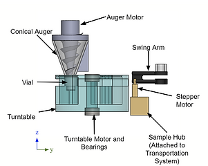
The sample enters a funnel ending in a screw conveyor. The rotation drives the sample into a vial that holds between 1cc and 5cc. The vials rest on a small lip, suspended inside a cut-out within the turntable. Then, the turntable rotates such that the sample vial is inside the lander vault to be picked up by the transportation system
Transportation: Gantry
Transportation: Sliding Rotary
Transportation: Cables


In order to communicate how the system should be created without power tools, we needed to create one ourselves. We attached two barrels to our original system, and built a small model to figure out how attaching the gutter to the roof, not the mud brick, would work.
The system would move by rotating the arm and sliding along the y-axis, allowing full range of motion within the needed space. Similarly to the gantry, the sample transport arm would have a handling mechanism within.
The position of the sample hub is controlled by winding and unwinding each motor to shorten or lengthen the cables, thus moving the hub. Since the hub is not attached rigidly to any surface, the hub must be a passive sample receiver. The sample hub will be pulled by a fifth cable into the measurement system plane and receive the sample before being released back to the instrument plane.
We concluded from our risk matrices that we would continue forward using the
turntable in conjunction with the gantry.
Again, to see these ideas in much more detail, check out the report or presentation.
Critical Design Review
With the turntable and the gantry selected, we determined motors, power requirements, materials for manufacturing, and specific parts for every system. We also identified our starting condition to be a funnel and our ending condition to be a vial receptacle at the instrument. As with the PDR and Spec and Planning, below can be found the CDR report and presentation for download. In the presentation, you can see a video of the full design interface.

To track the sample through the system: the screw conveyor moves the sample into the vials on the turntable which rotate inside and are picked up by the gantry system with a swing arm on the sample hub. The vial is then dropped off at the instrument wall, the gantry flips back around, and reloads the turntable with a new vial. With an established system, we calculated analysis of the critical components and sized the motors using those calculations.

Spring Semester Reviews
After Winter Break, our team moved into the Manufacturing review, Test plan review, and the Financial review. As the Manufacturing Engineer on the project, I created and approved manufacturing drawings, checking that design intent was conveyed and proper notation was applied. We sourced material and priced out the project. I created a manufacturing schedule based off time to machine and assemble each part. After the reviews, we were ready to begin manufacturing.


The Great Transition
Wrapping it up
As March hit, we were no longer allowed to work on the project in person. We had pushed hard on the manufacturing schedule and after 4 weeks of having at least one team member in the machine shop every day we had completed machining. Branden Adams, one of the team, took the physical assembly to his apartment and we finished the project remotely, working over Zoom. Our Exposition was cancelled (a more devastating blow than even graduation) and was replaced by a Senior Design Showcase (see beginning of page). We finished the semester with a final report and presentation to JPL and sent the physical prototype to California.

Conclusions